The objective of this Standard Operating Procedure Operation of UPS System is to outline the steps and guidelines for the proper operation of the Uninterruptible Power Supply (UPS) system to ensure continuous and reliable power supply to critical equipment during power disruptions or outages.
SOP for Operation of UPS System:
- OBJECTIVE:
- To lay down the Procedure for the operation of UPS System.
- SCOPE:
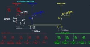
- This SOP is applicable to operation of UPS installed.
- RESPONSIBILITY:
- Technician/ Officer engineering shall be responsible for the proper execution of operation as per SOP.
- Engineering – Head shall be responsible for reviewing the SOP and for ensuring proper execution of SOP.
- ACCOUNTABILITY:
- Engineering – Head shall be accountable for proper implementation of the SOP.
- DEFINITIONS:
- Nil
- PROCEDURE:
- Precautions:
- Do not open or mutilate batteries.
- Do not attempt to alter any UPS or battery wiring or connectors. Attempting to alter wiring can cause injury.
- Ensure all power is disconnected before performing service.
- Batteries can present a risk of electrical shock or burn from high short-circuits current. The following precautions should be followed.
- Remove watches, rings or other metal handles.
- Use tools with insulated handles.
- Do not lay tools or metal parts on top of batteries.
- Wear rubber gloves and boots.
- Do not disconnect the batteries while the ups is ON.
- Disconnect the charging source prior to connecting or disconnecting terminals.
- Never dispose of batteries in fire. Batteries may explode when exposed to flame.
- Keep surroundings uncluttered, clean and free from excess moisture.
- Operation of UPS System :
- Procedure for switching the UPS to power the load from power off condition.
- Switch ON the circuit breaker and the battery breaker at the rear panel.
- As the breakers of UPS are turned ON the Line and bypass indicator will be lightened.
- After around 20 sec. of switching ON the UPS a click sound will be heard and the inverter gets connected to the output terminal.
- This screen indicates bypass AC input supply is present and the load is on Bypass.
- Initializing Window: After first connecting power to the UPS and closing the Q2 isolator, this message will appear on the LCD screen. It persists for about five seconds while the control firmware is UPS loaded. It is followed by a screen showing various messages with the time and date on the bottom line
- Operation of UPS System :
- Precautions:
RECTIF SWITCH OPEN
BATTERY SWITCH OPEN
OUTPUT SWITCH OPEN
hh.mm.ss dd. mm . yy
- Close the Rectifier input power switch Q1. After approximately 20 seconds the Module Mimic LED’s will change so that the Load on Inverter will light steady green and the Load on Bypass will extinguish.
BATTERY C.B. OPEN
OUTPUT SWITCH OPEN
HH .MM.SS DD.MM .YY
- Before closing the battery circuit breaker check the DC bus-bar voltage. From the above window press the ENTER key The Main Menu Window will display.
>MEASUREMENT >
FUNCTION
MAINTENANCE
SETUP
- Select MEASUREMENT and press ENTER key. Select BATTERY and the DC bus bar voltage will be displayed.
OUTPUT
INPUT
>BATTERY<
TEMPERATURE
BATTERY
VOLTAGE 432 [V]
CURRENT 001 [A]
CHARGE 000 [%]
- If the voltage indicated is satisfactory press the ESC key repeatedly until the display returns to the original window.
- Manually close the battery circuit breaker. This is located inside the battery cabinet (if used) or otherwise located adjacent to the battery racks. The Module Mimic indicator (4) Battery unavailable should extinguish. Several LED’s on the Battery state of charge bar graph will illuminate showing the battery state of charge. When the battery circuit breaker has been closed and the inverter has stabilized the screen will change to the default window. Default Window. The message shown below will be seen on the default screen whenever the UPS is operating normally.
NORMAL
OPERATION
HH:MM:SS DD.MM.YY
- The top lines display the UPS operational status and indicate alarm conditions when they occur; and line tour normally shows the time and date.
- Procedure for Switching the UPS into a Maintenance Bypass condition from normal operation.
- This procedure should be followed to transfer the load from the UPS inverter output to the maintenance bypass system. This may be required during UPS maintenance procedures.
MEASUREMENT
>FUNCTION<
MAINTENANCE
SETUP
- From the Default window press the ENTER key: the Main Menu Window will display.
- Select FUNCTION and press ENTER key.
| ? WRITE SAVE? ? MOVE EXIT C INPUT PASSWORD |
BATTERY TEST
GENERATOR
PANEL SETUP

- You now have access to all function windows. Press the DOWN arrow key until the cursors have selected NEXT PAGE – press the ENTER key.
MODEM CONNECTION
>ON/OFF UPS CONTROL <
RELOAD UPS DATA RESET
BUFFERS
- Press the DOWN arrow key until the cursors have selected. ON/ OFF UPS CONTROL – press the ENTER key.
>INVERTER ON <
LINE ON
RECTIFIER ON
RECTIFIER AUTO
- Ensure INVERTER is selected by the cursors and press the ENTER key:
The ON selection should be highlighted using the UP arrow key, rotate between the selections offered (in this case it will be ON or OFF) select OFF. Press the ENTER key to execute your command. The UPS inverter will now shut down and the load will transfer to the Bypass supply. The Display window can be returned to normal by operation of the ESCAPE key back through the various windows. The Module Mimic indicator Load on Bypass (3) will flash amber and the Load on Inverter indicator will extinguish.
- ABBREVIATIONS
- CRF No. : Change Request Form number
- UPS : Uninterrupted Power Supply.
- SOP : Standard operating procedure
- REFERENCES
- Operational & Maintenance Manual of UPS System
- DISTRIBUTION LIST
- SOP shall be distributed to the following departments Quality Assurance, Engineering as per user request.
- ANNEXURES
- Nil