The objective of this (Standard Operating Procedure) SOP For Preventive Maintenance of Ampoule Filling and Sealing Machine is to outline the steps for performing preventive maintenance on the Ampoule Filling and Sealing Machine to ensure its optimal performance, reliability, and longevity. Preventive maintenance should be performed at regular intervals as specified in the machine manufacturer’s guidelines or as determined by the maintenance team based on the machine’s usage and condition.
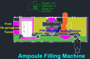
SOP For Preventive Maintenance of Ampoule Filling and Sealing Machine
- OBJECTIVE:
- This SOP is describing the Preventive Maintenance procedure of the Ampoule Filling and Sealing Machine.
- SCOPE:
- This SOP is applicable for the Preventive Maintenance of the Ampoule Filling and Sealing Machine installed in the Production department.
- RESPONSIBILITY:
- The technician/ Operator shall be responsible for the proper execution of preventive maintenance as per SOP.
- Engineering – The head shall be responsible for reviewing the SOP and for ensuring proper execution of preventive maintenance.
- ACCOUNTABILITY:
- Engineering – Head shall be accountable for proper implementation of the SOP.
- DEFINITIONS:
- Nil

- PROCEDURE:
- Preventive maintenance shall be executed as per the SOP No.: SOP/EN/XXXYYY– Execution of Preventive Maintenance.
- Ensure that the spare parts are available at the time of preventive maintenance.
- Preventive Maintenance – Mechanical
- Checking of fasteners
- Check that all the fasteners / mounting bolts of the filling, and sealing machine are properly tightened. There should not be any loose bolts.
- If found loose, tighten the bolts and nuts by using suitable spanners.
- Checking shall be done monthly.
- Checking of pneumatic tubes and fittings
- Physically check the pneumatic tubes and connectors for any damage/leakage. There should not be any damage/leakage in the tubes and connectors.
- If any damage/leak is observed, replace the tube/connector.
- Checking shall be done monthly.
- Checking of waste gas ducting/exhaust gas piping
- Check the tightness of end connections if required tighten the same.
- Check and clean the duct for any kind of obstruction or plugging.
- Checking shall be done yearly.
- Check the exhaust blower on a monthly basis.
- Checking of the gas piping
- Check and clean the gas line filters.
- Check the end connection of gas lines.
- Check the hose connection of gas piping for any leakages; if required replaces the same.
- Check the performance of pressure regulator.
- Check for the gas backflow preventer installed between gas connection point and the burner.
- Clean the torch flames; dirty mixing nozzles and pressure nozzles leads to irregular torch flames and make it difficult to adjust.
- Check the torch nozzles orifice for wear.
- Check the position of pointing tongs ensures that it must not be within the range of torch limits.
- The checking shall be done on monthly basis.
- Checking of Valve pumps for filling
- Check the valve filling pumps for any damaged. If found damaged /worn out, replace the same.
- Checking shall be done six monthly.
- Checking of belts
- Check the timing belts of the filling machine and all the conveyor belts of the filling,
- Physically check the wear and tear of conveyor belts, if required rectify or replace the conveyor belts.
- Checking shall be done monthly.
- Checking and lubrication of bearings, chains, gears and sprockets.
- Check sprockets, gears, chains and cams for any damage. If found damaged, replace the same.
- Lubricate bearings, cams, gears, chains and sprockets with the help of a grease gun.
- Checking shall be done monthly.
- Checking of Cutting assembly
- Check the clippers physically.
- Check the condition of the clipper springs.
- Checking shall be done monthly.
- Checking of Cams
- Check the cams for radial play.
- Check the cam bushes and connecting shafts.
- Checking shall be done monthly.
- Recommended/Identical Oil and grease for the lubrication as follows.
| Sr.No. | Lubricants | Type | Grade | Interval | Application |
| 1 | Grease | Mineral Oil | NLGI 0,1,2 | 1000 Hours | Bearing, Bushing, slides rollers, and cam followers |
| 2 | Oil | Mineral Oil | SAE 80W – 90, SAE 85W-140 | 300 Hrs | Gears, bearings and chains |
- Checking of Valves
- Check the valves for smoothly movements, if the operating handle of valve is found jammed or stuck, then open the valve and carry out the maintenance as follows.
- Switch off the supply system.
- Close the nearby upside and down side valves.
- Open the end connections and dismantle the valve.
- If gasket found damaged (cut, leached, deform, shape and size change) change the same.
- After physically checking of valve, refit in to the system and check for leakage and valve operation if found satisfactorily then it is okay otherwise replace the valve.
- Check frequency shall be quarterly.
- Cleaning of Utility inline Filters cartridge
- Check the reading of differential pressure gauges; if it filters get choked and not giving uniform flow; then the cleaning of cartridge filter is necessary.
- To clean the cartridge filter follows the following procedure.
- Close the inlet and outlet valves of filter.
- Open the drain plug, and drain out the hold water form filter housing; through close drain piping.
- Loose the body flange of cartridge filter housing.
- Remove the cartridge filter; check the condition of filter; if it is found damaged; then replace the same or sterilized the cartridge filter and check for the integrity testing as per “Procedure for Cleaning and Operation of Filter Integrity Test Instrument” SOP No.: SOP/PR/XXXYYY
- Frequency of checking and replacement of filter cartridge shall be as needed.
- Checking of Filter housing
- Physical verify the filter housing for any damaged, shape change, dents; surface roughness and end connections. If found, then rectify or replace the same.
- Check frequency shall be half yearly
- Checking of printer
- Check the printer for paper alignment and printer cartridge ribbon.
- Check frequency shall be half yearly
- Preventive Maintenance – Electrical
- Checking of terminals and wiring
- Ensure that the main electrical supply to the machine is switched OFF.
- Visually check all the power and control wiring and terminals in the electrical panel and for control elements mounted on the machine for any loose connection and damage.
- Check and ensure by using the screwdriver that all the wires are properly tightened at the distribution terminals inside the electrical panel and on the terminals of all the control elements.
- Checking shall be done six monthly.
- Checking motor
- Check the insulation resistance of motor winding with the help of megger.
- Check the phase continuity and winding continuity of motor with the help of tong tester.
- Physically check the motor terminal box and terminal connections.
- Check the voltage drawn by motor with the help of multimeter
- Check the current drawn by motor with the help of tong tester.
- Physically check the direction of rotation; it should be as per recommended direction.
- Checking shall be done after every six month.
- Checking of PLC
- Check the PLC for blinking of LED
- Check the display
- Check the wiring contacts, if required tight the same.
- Checking of PLC shall be done after every six month
- Checking of contactors
- Switch OFF the Electrical supply to the Machine.
- Remove all the power and control wires from the contactor terminals
- Remove the dust from the control panel with help of air blower.
- Remove the contactor from the panel and visually check all the contacts for the signs of pitting and deposit of carbon on the contacts.
- Clean the contacts, terminals and all the moving parts of the contactor by spraying contactor cleaner, replace the contacts if found damaged / welded.
- Put back the contactor in the panel and re-terminate all the power and control wires properly to their original locations.
- Check the earthing of the panel body.
- A good earthing shall show less than 2 Volts between the Neutral Wire of the Incoming Power supply and Panel Body.
- Checking of contactors shall be done six monthly.
- Checking of clutches
- Check the proper functioning of clutches.
- Check the electrical wiring and connections of clutches.
- Checking of clutches shall be done monthly.
- Check the stock of recommended spare part list as follows;
- List of recommended Spare part list; checking frequency shall be after every six month.
| Sr. No. | Description | Part No. | Quantity (Nos.) |
| 1 | BALL BEARING. | ||
| 2 | CAM FOLLOWER. | ||
| 3 | BALL BEARING. | ||
| 4 | BUSH. | ||
| 5 | DRUM CAM. | ||
| 6 | BALL BEARING. | ||
| 7 | CAM FOLLOWER. | ||
| 8 | SLIDE SIDE PLATE. | ||
| 9 | BALL BEARING. | ||
| 10 | BALL BEARING. | ||
| 11 | BALL BEARING. | ||
| 12 | RACK | ||
| 13 | DRUM CAM. | ||
| 14 | CAM FOLLOWER. | ||
| 15 | BALL BEARING. BALL BEARING. | ||
| 16 | DRUM CAM. | ||
| 17 | CENTERING ROLLER. | ||
| 18 | DISC ROLLER. | ||
| 19 | PIN. | ||
| 20 | LINEAR BEARING. | ||
| 21 | BALL BEARING | ||
| 22 | PLATE CAM | ||
| 23 | PLATE CAM. | ||
| 24 | CAM FOLLOWER. | ||
| 25 | CLUTCH WIRE (BIG). | ||
| 26 | CLUTCH WIRE (SMALL). | ||
| 27 | LINEAR BEARING. | ||
| 28 | SOLONOID. | ||
| 29 | SOLONOID NEEDLE BAR PIN. | ||
| 30 | PLATE CAM. | ||
| 31 | BALL BEARING. | ||
| 32 | IDLER GEAR BUSH. | ||
| 33 | BALL BEARING. | ||
| 34 | HOLDER PIN. | ||
| 35 | GUIDE BUSH. | ||
| 36 | LOCK NUT. | ||
| 37 | CLUTCH HUB. | ||
| 38 | HUB SUPPORT COLLER. | ||
| 39 | BALL CATCH LEVER. | ||
| 40 | STEEL BALL. | ||
| 41 | BALL CATCH. | ||
| 42 | SPRING. | ||
| 43 | CHUCK NUT. | ||
| 44 | SENSOR | ||
| 45 | ADJUSTING SCREW. | ||
| 46 | BALL BEARING. | ||
| 47 | BALL BEARING. | ||
| 48 | BALL BEARING. | ||
| 49 | DRIVE RACK | ||
| 50 | BALL BEARING. | ||
| 51 | BALL BEARING. | ||
| 52 | DRUM CAM. | ||
| 53 | CLUTCH UNIT. | ||
| 54 | PRESSURE LUPPER | ||
| 55 | SPRING STOPPER. | ||
| 56 | LUPPER SPRING. | ||
| 57 | CONNECTING BEARING. | ||
| 58 | CONNECTING BEARING. | ||
| 59 | BALL BEARING. | ||
| 60 | BALL BEARING. | ||
| 61 | CAM FOLLOWER. | ||
| 62 | BALL BEARING. | ||
| 63 | BALL BEARING. | ||
| 64 | BOTTOM PLATE. | ||
| 65 | SEGMENT BLOCK. | ||
| 66 | BALL BEARING. | ||
| 67 | BALL BEARING. | ||
| 68 | SEGMENT GUIDE BLOCK (BOTTOM). | ||
| 69 | SEGMENT GUIDE BLOCK (TOP). | ||
| 70 | OPTIC FIBRE SENSOR. | ||
| 71 | DRIVE FLANGE. | ||
| 72 | LOCKER POWL HUB BALL BEARING. | ||
| 73 | HUB SPROCKET. | ||
| 74 | LOCKER POWL. | ||
| 75 | POWL SPRING. | ||
| 76 | LOCK LEVER. | ||
| 77 | LEVER BUSH. | ||
| 78 | SOLONIDE | ||
| 79 | LINK PLATE. | ||
| 80 | SPRING. | ||
| 81 | SPRING. | ||
| 82 | RUBBER ROLLER. | ||
| 83 | BUSH | ||
| 84 | GEAR. | ||
| 85 | GEAR. | ||
| 86 | BURNER ADAPTOR. | ||
| 87 | BURNER. | ||
| 88 | MIXTURE UNIT. | ||
| 89 | CONNECTING BEARING. | ||
| 90 | CONNECTING BEARING. |
- Checking for safety alarms
- Check the system for the following alarms; the frequency shall be after every six months.
| 1. | Pump Overload The pump stops working as the sensor is not position. | Audio alarm is activated. OIT (operator Interface Terminal) displays the following alarm message. (PUMP OVERLOAD) | The machine stops. Place the sensor in position. Reset the fault by pressing the RESET button |
| 2 | MACHINE JAM The segment stops when the sensor is not in correct position. | Audio alarm is activated. OIT (operator Interface Terminal) displays the following alarm message. (MACHINE JAM) | The machine stops. Place the sensor in position. Reset the fault by pressing the RESET button. |
| 3 | EMERGENCY STOP Emergency push button is pressed. | Audio alarm is activated. OIT (operator Interface Terminal) displays the following alarm message. (EMERGENCY STOP) | The machine stops. Release the emergency push button. Reset the fault by pressing the RESET button. |
| 4 | MOTOR OVERLOAD The main motor stops so the conveyor motor also stops. | Audio alarm is activated. OIT (operator Interface Terminal) displays the following alarm message. (MOTOR OVERLOAD ) | The machine stops. Reset the fault by pressing the RESET button after the motor load is set. |
| 5 | LOW PRESSURE N2 The nitrogen pressure is low in the flow meter. | Audio alarm is activated. OIT (operator Interface Terminal) displays the following alarm message. (LOW PRESSURE N2) | The machine stops. Reset the fault by pressing the RESET button after the required pressure is set. |
| 6 | LOW PRESSURE O2 The Oxygen pressure is low in the flow meter. | Audio alarm is activated. OIT (operator Interface Terminal) displays the following alarm message. (LOW PRESSURE O2) | The machine stops. Reset the fault by pressing the RESET button after the required pressure is set. |
| 7 | LOW PRESSURE LPG The LPG pressure is low in the flow meter. | Audio alarm is activated. OIT (operator Interface Terminal) displays the following alarm message. (LOW PRESSURE LPG) | The machine stops. Reset the fault by pressing the RESET button after the required pressure is set. |
| 8 | DOOR OPEN The door is the open position i.e. the sensor is in improper position. | Audio alarm is activated. OIT (operator Interface Terminal) displays the following alarm message (DOOR OPEN) | The machine stops. Set the sensor in correct position. Reset the fault by pressing the RESET button. |
| 9 | LAF OFF LAF system stops working. | Audio alarm is activated. OIT (operator interface Terminal) displays the following alarm message (LAF OFF) | The machine stops. Reset the fault by pressing the RESET button. |
| 10 | MINIMUM ACCUMULATION AT INFEED Less no of ampoules at infeed conveyor in Auto Mode Operation. | Audio alarm is activated. OIT (operator Interface Terminal) displays the following alarm message (MINIMUM ACCUMULATION AT INFEED) | The machine stops. Reset the fault by pressing the Reset Button after ensuring enough ampoules at infeed. |
- Post Preventive Maintenance – Check List
- Record the Preventive Maintenance details as per the Format No.: SOP/EN/XXXYYY“Preventive Maintenance Checklist & Record for Ampoule Filling and Sealing Machine”.
- Whenever any modifications and major works are carried out to the equipment, the same shall be mentioned in the equipment history card as per the respective SOP.
- Connect the equipment main power supply and start the equipment.
- Ensure that the equipment is running smoothly, without any abnormality.
- If any abnormality is observed in the above, same will be attended in co-ordination with User department Head.
- ABBREVIATIONS:
- CRF No. : Change Request Form number
- QA : Quality Assurance
- MMI : Man Machine Interface
- PLC : Programmable Logical Controller
- LED : Light Emitting Diode
- LAF : Laminar Air Flow
- REFERENCES:
- Operational & Maintenance Manual of Ampoule filling and sealing machine
- DISTRIBUTION LIST:
- SOP shall be distributed to following departments Quality Assurance, Engineering as per user request.
- ANNEXURES:
- Preventive maintenance checklist and record for : SOP/EN/XXXYYY Ampoule Filling and Sealing Machine
PREVENTIVE MAINTENANCE CHECKLIST & RECORD FOR AMPOULE FILLING AND SEALING MACHINE
| Equipment Name | Location | ||
| Equipment ID | Frequency |
| Things to be done: | Check List | Remarks |
| Monthly Check List | ||
| Checking of the gas piping for leakages. | ||
| Check the performance of pressure regulator. | ||
| Check the orifice nozzle for wear. | ||
| Check the position of pointing tongs ensures that it must not be within the range of torch flame. | ||
| Checking of fasteners. | ||
| Checking of pneumatic tubing and fittings. | ||
| Checking of conveyor belts. | ||
| Checking of lubrication of bearings, chains gears and sprockets. | ||
| Checking of Clutches. | ||
| Check the exhaust blower. | ||
| Checking of Cams. | ||
| Checking of cutting assembly. | ||
| Quarterly Check List | ||
| Checking of valves. | ||
| Half Yearly Check List | ||
| Checking of printer. | ||
| Checking of pumps. | ||
| Checking of filter housing. | ||
| Checking of terminals and wiring. | ||
| Checking of motor. | ||
| Check the stock of recommended spare parts. | ||
| Checking of safety alarms. | ||
| Yearly check List | ||
| Checking of waste gas ducting for leakage and any obstruction or plugging. |