The purpose of this Standard Operating Procedure for Preventive Maintenance of Vial Sterilization Depyrogenation Tunnel is to provide guidelines and instructions for the preventive maintenance of the Vial Sterilization Depyrogenation Tunnel to ensure its optimal performance, compliance with sterilization and depyrogenation requirements, and to minimize the risk of contamination.
SOP for Preventive Maintenance of Vial Sterilization Depyrogenation Tunnel
- OBJECTIVE:
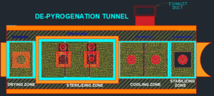
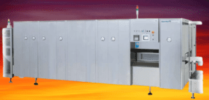
- This SOP is describing the preventive maintenance procedure of vial sterilization & depyrogenation tunnel.
- SCOPE:
- This SOP is applicable for preventive maintenance of vial sterilization & depyrogenation tunnel installed in Production department.
- RESPONSIBILITY:
- Technician/ Operator shall be responsible for proper execution of preventive maintenance as per SOP.
- Engineering – Head shall be responsible for reviewing the SOP and for ensuring proper execution of preventive maintenance
- ACCOUNTABILITY:
- Engineering – Head shall be accountable for proper implementation of the SOP.
- DEFINITIONS:
- Nil
- PROCEDURE:
- Preventive maintenance shall be executed as per the SOP No.: SOP/EN/XXXYYY- Execution of Preventive Maintenance.
- Ensure that the spare parts are available at the time of preventive maintenance.
- Preventive Maintenance: – Mechanical
- Check the filter for dry zone pre-filter as follows
- Loosen the filter fame bolts and remove frame.
- Loosen the filter clamp.
- Loosen the bolts and remove the filter and check and clean the filter as per filter cleaning SOP No. SOP/EN/XXXYYY, when preventive maintenance activity is performed
- After cleaning and drying the filters fix the filter on the frame.
- Tighten the bolts and adjust the clamps position properly.
- Ensure that the mounting of the filter is done properly on the frame.
- Position and mount the pre filter with frame and tighten the bolts.
- Ensure that the pre-filter is mounted properly and will function as per requirement.
- Frequency to check the dry zone filter shall be Monthly.
- Replacement Procedure for dry zone HEPA filter as follows
- Loosen the clamps with the help of spanner.
- With utmost care remove the HEPA Filter and check the condition of HEPA filter
- Replace the old HEPA filter with New HEPA filter with utmost care, hold the HEPA filters in such a position so that no damage is done to the filters while mounting the HEPA filters.
- Carefully hold and position the filter at desired place and make sure that the mounting is done in a proper way.
- After mounting hold the clamp in proper position so that it holds the filter.
- Tighten the bolts back to the clamp.
- Replacement frequency of dry zone HEPA filter shall be 2 years or if the integrity fails during revalidation.
- Check the filter for hot zone pre-filter as follows
- With the help of a nut, loosen the front plate on to the pre-filter.
- Remove the front plate from the front side.
- Remove the filter manually with utmost care.
- Check the filter and clean the filter.
- After cleaning the pre-filter mount the pre-filter with utmost care.
- After proper adjustment, attached the front plate.
- With the help of a nut, tighten the front plate on to the pre-filter.
- Checking of the hot zone pre filter frequency shall be Monthly.
- Replacement Procedure of Hot zone HEPA filter as follows
- Switch off the power supply
- Loosen the bolts on the heater bank and carefully remove the heaters.
- Remove the clamping studs from all sides with the help a spanner and also remove the filter mounting bar at the top.
- Remove the high temperature HEPA filters with gaskets.
- Replace the old HEPA filter with new HEPA filter; insert the high temperature HEPA filters with gasket on the downstream side.
- Extreme care should be taken while placing the filters and tighten the stud.
- After proper mounting attach all the studs with the filter mounting bars again.
- Attach the heater bank as before.
- Replacement frequency of hot zone HEPA filter shall be 2 years or if the integrity fails during revalidation.
- Check the filter for cooling zone pre-filter as follows
- Loosen the bolts over the top plate.
- Remove the top plate.
- Carefully remove the pre-filter from the slot provided for the same.
- Check the filter and clean the filter.
- After cleaning of pre-filter refit the filter in slot provided for the same.
- Slowly press the filter from top so that it moves inside.
- Ensure that the mounting is done properly.
- Attach the top plate and tighten the bolts.
- Checking of the cooling zone pre filter frequency shall be Monthly.
- Replacement Procedure for cooling zone HEPA-filter as follows
- Loosen the clamp with the help of spanner.
- With utmost care, remove the HEPA filter.
- Replace the old HEPA filter with new HEPA filter with utmost care, hold the HEPA filters in such a position so that no damage is done to the filters while mounting the HEPA filters.
- Carefully hold and position the filter at desired place and make sure that he mounting is done in a proper way.
- After mounting hold the clamp in proper position so that it holds the filter.
- Tighten the blots back to the clamps.
- Replacement frequency of cooling zone HEPA filter shall be 2 years or if the integrity fails during revalidation.
- Checking of Conveyor in case of breakage of vials
- The checking and cleaning of the conveyor and the side plates near the conveyor is essential when the breakage of the containers takes place.
- The guards at front as well as from side should be taken out.
- The reason for breakage of the vials should be found and the necessary action should be taken.
- The broken vials should be cleaned with a piece of cloth.
- The vials must be cleaned from the side plate as well as from the bottom of the conveyor. This should be done so that the vials does not get stuck between the conveyors rollers at the Dry Zone and Cooling Zone side and cause any damage to the machine.
- Checking frequency monthly.
- Top side cleaning
- The cleaning of the tunnel from the top side should be done so that is accumulated at the top of the tunnel.
- The cleaning frequency shall be monthly.
- Lubrication and maintenance of the hot air fan
- Check the hot air fan for the lubrication.
- Check the Lubrication for operation at the appropriate lubrication nipple.
- For this lubrication, high temperature bearing grease must be used.
- The high temperature bearing grease can be obtained from the manufacturer.
- Checking frequency shall be after every six month.
- Cleaning of heater banks
- The cleaning of the heater banks is done by cleaning the heater element with a clean brush from both sides.
- The cleaning frequency shall be after every six month.
- Replacement procedure of the tubular heater element
- Switch off the power supply.
- Take off the paneling on the left-hand tunnel side as in the direction of travel.
- Unscrew screws; take off perforated metal sheet metal panel E.
- Unscrew acorn nut and all rounds and take off together with the washers.
- Move the complete heater assembly B out of the studs and deposit on a surface with sufficient carrying capacity.
- Unscrew nuts and then take off the sheet metal panel C.
- Disconnect the electric supply wires from the terminals of the faulty tubular heater element out of brackets and remove.
- The installation of a new tubular heater element is carried out in the reverse order.
- Make sure that all screws, nuts and washers are put back again.
- Tighten screws and nuts evenly.
- Checking of conveyor belts
- Check the conveyor belts A and B regularly for wear and have them replaced by qualified technicians if necessary.
- The drive pulleys C and D must be checked every 6 months for their general condition and particularly for ageing cracks.
- If damage is found, it is advisable to change the drive pulleys.
- This works requires special knowledge and should be carried out by a qualified fitter.
- Check the shear pin, to safeguard against damage to the drive and to the conveyor belts.
- If the equipment jams, the shear pin breaks off. Knock out the remnants from the sprocket and the shaft, then insert a new shear pin and secure with the serrated lock washers and nuts.
- Checking of conveyor belt frequency shall be after every six month.
- Checking and Tightening the roller chain
- Check the tension of the roller chain, if necessary retightening is done after slackening of the roller chain.
- Checking of roller chain shall be done after every six month.
- Cleaning of Chilling Coil
- Chilling coil is one of the critical components of the tunnel.
- Therefore the mounting of the coil should be done carefully and with utmost care.
- The cooling coil is mounted from the back side where the coil is mounted on the bracket provided for the same purpose.
- The cleaning of the chilling coil is also important because due to continuous operation some amount of dust can get accumulated on the fins.
- Therefore to remove the dust, air should be sprayed gently so that no damage is done to the fins and the coil.
- Clean the drain pipe regularly.
- Cleaning frequency shall be after every three month.
- Checking of Exhaust
- Check the exhaust for exhaust flow restriction.
- Checking frequency shall be done after every month.
- Checking of printer
- Check the printer for paper alignment and printer cartridge ribbon.
- Check the availability of spares before doing preventive maintenance.
- Checking of alarms
- Checking of the alarms shall be after every six month
| Sr. No. | Alarms and Conditions | Alarm Message | Control Action |
| 1 | DRY ZONE BLOWER OVERLOAD The DZ blower stops working due to overload. | Audio alarm is activated. OIT (operator Interface Terminal) displays the following alarm message (DRY ZONE BLOWER OVERLOAD) | The machine stops. Reset the fault by pressing the RESET button after the blower load is set. |
| 2 | HOT ZONE MOTOR OVERLOAD The HZ blower stops working due to overload. | Audio alarm is activated. OIT (operator Interface Terminal) displays the following alarm message (HOT ZONE MOTOR OVERLOAD) | The machine stops. Reset the fault by pressing the RESET button after the blower load is set. |
| 3 | COOL ZONE BLOWER OVERLOAD The CZ blower stops working due to overload. | Audio alarm is activated. OIT (operator Interface Terminal) displays the following alarm message (COOL ZONE BLOWER OVERLOAD) | The machine stops. Reset the fault by pressing the RESET button after the blower load is set. |
| 4 | DZ EXTRACTOR BLOWER OVERLOAD The DZ extractor motor stops working due to overload. | Audio alarm is activated. OIT (operator Interface Terminal) displays the following alarm message (VAPOUR EXTRACTOR BLOWER OVERLOAD) | The machine stops. Reset the fault by pressing the RESET button after the motor load is set. |
| 5 | CZ RECIRCULATING BLOWER OVERLOAD The CZ recirculation motor stops working due to overload. | Audio alarm is activated. OIT (operator Interface Terminal) displays the following alarm message (CZ RECIRCULATING BLOWER OVERLOAD) | The machine stops. Reset the fault by pressing the RESET button after the blower load is set. |
| 6 | CONVEYOR MOTOR OVERLOAD The conveyor motor stops working due to tripping of overload relay. | Audio alarm is activated. OIT (operator Interface Terminal) displays the following alarm message (CONVEYOR MOTOR OVERLOAD) | The machine stops. Reset the fault by pressing the RESET button after the blower load is set. |
| 7 | ENCODER FAULT The conveyor stops as well as the heater banks stop. | Audio alarm is activated. OIT (operator Interface Terminal) displays the following alarm message (ENCODER FAULT) | The machine stops. Reset the fault by pressing the RESET button after the wire in the encoder is connected. |
| 8 | EMERGENCY STOP Emergency push button is pressed. | Audio alarm is activated. OIT (operator Interface Terminal) displays the following alarm message (EMERGENCY STOP) | The machine stops. Reset the fault by pressing the RESET button after the blower load is set. |
| 9 | LOW DIFF. PRESSURE ABOVE DZ HEPA The pressure above dry zone HEPA filter is low. | Audio alarm is activated. OIT (operator Interface Terminal) displays the following alarm message (LOW DIFF. PRESSURE ABOVE DRY ZONE HEPA ) | The machine stops. Reset the fault by pressing the RESET button after required pressure is set and the blowers are on. |
| 10 | HIGH DIFF. PRESSURE ABOVE DZ HEPA The pressure above dry zone HEPA filter is high. | Audio alarm is activated. OIT (operator Interface Terminal) displays the following alarm message (HIGH DIFF. PRESSURE ABOVE DRY ZONE HEPA ) | The machine stops. Reset the fault by pressing the RESET button after required pressure is set and the blowers are on. |
| 11 | LOW DIFF. PRESSURE ABOVE HZ HEPA The pressure above hot zone HEPA filter is low. | Audio alarm is activated. OIT (operator Interface Terminal) displays the following alarm message (LOW DIFF. PRESSURE ABOVE HOT ZONE HEPA ) | The machine stops. Reset the fault by pressing the RESET button after required pressure is set and the blowers are on. |
| 12 | HIGH DIFF. PRESSURE ABOVE HZ HEPA The pressure above hot zone HEPA filter is high. | Audio alarm is activated. OIT (operator Interface Terminal) displays the following alarm message (HIGH DIFF. PRESSURE ABOVE HOT ZONE HEPA ) | The machine stops. Reset the fault by pressing the RESET button after required pressure is set and the blowers are on. |
| 13 | LOW DIFF. PRESSURE ABOVE CZ HEPA The pressure above cool zone HEPA filter is low. | Audio alarm is activated. OIT (operator Interface Terminal) displays the following alarm message (LOW DIFF. PRESSURE ABOVE COOL ZONE HEPA ) | The machine stops. Reset the fault by pressing the RESET button after required pressure is set and the blowers are on. |
| 14 | HIGH DIFF. PRESSURE ABOVE CZ HEPA The pressure above cool zone HEPA filter is high. | Audio alarm is activated. OIT (operator Interface Terminal) displays the following alarm message (HIGH DIFF. PRESSURE ABOVE COOL ZONE HEPA ) | The machine stops. Reset the fault by pressing the RESET button after required pressure is set and the blowers are on. |
| 15 | DRY ZONE ROOM PRESSURE LOW The pressure across Dry Zone is low. | Audio alarm is activated. OIT (operator Interface Terminal) displays the following alarm message (DIFF. PRESSURE DRY ZONE W.R.T ROOM LOW) | The machine stops. Reset the fault by pressing the RESET button after required pressure is set and the blowers are on. |
| 16 | DRY ZONE ROOM PRESSURE HIGH The pressure across Dry Zone is high. | Audio alarm is activated. OIT (operator Interface Terminal) displays the following alarm message (DIFF. PRESSURE DRY ZONE W.R.T ROOM HIGH) | The machine stops. Reset the fault by pressing the RESET button after required pressure is set and the blowers are on |
| 17 | HOT ZONE ROOM PRESSURE LOW The pressure across Hot Zone is low. | Audio alarm is activated. OIT (operator Interface Terminal) displays the following alarm message (DIFF. PRESSURE HOT ZONE W.R.T ROOM LOW) | The machine stops. Reset the fault by pressing the RESET button after required pressure is set and the blowers are on |
| 18 | HOT ZONE ROOM PRESSURE HIGH The pressure across Hot Zone is high. | Audio alarm is activated. OIT (operator Interface Terminal) displays the following alarm message (DIFF. PRESSURE HOT ZONE W.R.T ROOM HIGH) | The machine stops. Reset the fault by pressing the RESET button after required pressure is set and the blowers are on |
| 19 | COOL ZONE ROOM PRESSURE LOW The pressure across Cool Zone is low. | Audio alarm is activated. OIT (operator Interface Terminal) displays the following alarm message (DIFF. PRESSURE COOL ZONE W.R.T ROOM LOW) | The machine stops. Reset the fault by pressing the RESET button after required pressure is set and the blowers are on. |
| 20 | COOL ZONE ROOM PRESSURE HIGH The pressure across Cool Zone is high. | Audio alarm is activated. OIT (operator Interface Terminal) displays the following alarm message (DIFF. PRESSURE COOL ZONE W.R.T ROOM HIGH) | The machine stops. Reset the fault by pressing the RESET button after required pressure is set and the blowers are on. |
| 21 | DZ TEMPERATURE HIGH The drying zone temperature is high. | Audio alarm is activated. OIT (operator Interface Terminal) displays the following alarm message (DRY ZONE TEMPERATURE HIGH) | The machine stops. Reset the fault by pressing the RESET button after the required temperature is set. |
| 22 | CZ TEMPERATURE HIGH The cooling zone temperature is high. | Audio alarm is activated. OIT (operator Interface Terminal) displays the following alarm message (COOL ZONE TEMPERATURE HIGH) | The machine stops. Reset the fault by pressing the RESET button after the required temperature is set. |
| 23 | HZ TEMPERATURE COMPARE FAULT The HZ temperature between entry and exit is more than 600 | Audio alarm is activated. OIT (operator Interface Terminal) displays the following alarm message (HOT ZONE TEMPERATURE COMPARE FAULT ) | The machine stops. Reset the fault by pressing the RESET button after the required temperature is set. |
| 24 | HOT ZONE TEMPERATURE. OVERSHOOT (EXTERNAL) The hot zone overshoot temperature is low. | Audio alarm is activated. OIT (operator Interface Terminal) displays the following alarm message (HOT ZONE TEMPERATURE OVERSHOOT (EXTERNAL)) | The machine stops. Reset the fault by pressing the RESET button after the required temperature is set. |
| 25 | LOW TEMPERATURE HZ ENTRY The hot zone temperature at entry is low. | Audio alarm is activated. OIT (operator Interface Terminal) displays the following alarm message (LOW TEMPERATURE HOT ZONE ENTRY) | The machine stops. Reset the fault by pressing the RESET button after the temperature is set properly. |
| 26 | HIGH TEMPERATURE HOT ZONE ENTRY The hot zone temperature at entry is high. | Audio alarm is activated. OIT (operator Interface Terminal) displays the following alarm message (HIGH TEMPERATURE HOT ZONE ENTRY) | The machine stops. Reset the fault by pressing the RESET button after the temperature is set properly. |
| 27 | LOW TEMPERATURE HOT ZONE EXIT The hot zone temperature at exit is low. | Audio alarm is activated. OIT (operator Interface Terminal) displays the following alarm message (LOW TEMPERATURE HOT ZONE EXIT) | The machine stops. Reset the fault by pressing the RESET button after the temperature is set properly. |
| 28 | HIGH TEMPERATURE HOT ZONE EXIT The hot zone temperature at exit is high. | Audio alarm is activated. OIT (operator Interface Terminal) displays the following alarm message (HIGH TEMPERATURE HOT ZONE EXIT) | The machine stops. Reset the fault by pressing the RESET button after the temperature is set properly. |
| 29 | CHILLED WATER TEMPERATURE HIGH The chilled water temperature is high. | Audio alarm is activated. OIT (operator Interface Terminal) displays the following alarm message (CHILLED WATER TEMPERATURE HIGH) | The machine stops. Reset the fault by pressing the RESET button after the required temperature is set. |
| 30 | CHILLING COIL TEMPERATURE HIGH The chilling coil temperature is high | Audio alarm is activated. OIT (operator Interface Terminal) displays the following alarm message (CHILLING COIL TEMPERATURE HIGH) | The machine stops. Reset the fault by pressing the RESET button after the required temperature is set. |
| 31 | DZ EXTRACTOR TEMPERATURE HIGH The DZ extractor temperature is high. | Audio alarm is activated. OIT (operator Interface Terminal) displays the following alarm message (DZ EXTRACTOR TEMPERATURE HIGH) | The machine stops. Reset the fault by pressing the RESET button after the required temperature is set. |
| 32 | DZ RTD FAULT The drying zone RTD error occurs when the sensor is not in position. | Audio alarm is activated. OIT (operator Interface Terminal) displays the following alarm message (DRY ZONE RTD FAULT ) | The machine stops. Reset the fault by pressing the RESET button after the sensor is set in position. |
| 33 | HOT ZONE ENTRY RTD FAULT The entry hot zone RTD error occurs when the sensor is not in position. | Audio alarm is activated. OIT (operator Interface Terminal) displays the following alarm message (HOT ZONE ENTRY RTD FAULT ) | The machine stops. Reset the fault by pressing the RESET button after the sensor is set in position. |
| 34 | HOT ZONE EXIT RTD FAULT The exit hot zone RTD error occurs when the sensor is not in position. | Audio alarm is activated. OIT (operator Interface Terminal) displays the following alarm message (HOT ZONE EXIT RTD FAULT ) | The machine stops. Reset the fault by pressing the RESET button after the sensor is set in position. |
| 35 | COOLING ZONE RTD FAULT The cooling zone RTD error occurs when the sensor is not in position. | Audio alarm is activated. OIT (operator Interface Terminal) displays the following alarm message (COOL ZONE RTD FAULT ) | The machine stops. Reset the fault by pressing the RESET button after the sensor is set in position. |
| 36 | CHILLING COIL RTD FAULT The chilling coil RTD error occurs when the sensor is not in position. | Audio alarm is activated. OIT (operator Interface Terminal) displays the following alarm message (CHILLING COIL RTD FAULT) | The machine stops. Reset the fault by pressing the RESET button after the sensor is set in position. |
| 37 | CHILLED WATER RTD FAULT The chilled water RTD error occurs when the sensor is not in position | Audio alarm is activated. OIT (operator Interface Terminal) displays the following alarm message (CHILLED WATER RTD FAULT) | The machine stops. Reset the fault by pressing the RESET button after the sensor is set in position. |
| 38 | DZ PRESSURE TRANSDUCER FAULT The pressure transducer fault occurs due to sensor not in position. | Audio alarm is activated. OIT (operator Interface Terminal) displays the following alarm message (DRYING ZONE PRESSURE TRANSDUCER FAULT W.R.T ROOM) | The machine stops. Reset the fault by pressing the RESET button after the sensor is set in position. |
| 39 | HZ PRESSURE TRANSDUCER FAULT The pressure transducer fault occurs due to sensor not in position. | Audio alarm is activated. OIT (operator Interface Terminal) displays the following alarm message (HOT ZONE PRESSURE TRANSDUCER FAULT W.R.T ROOM) | The machine stops. Reset the fault by pressing the RESET button after the sensor is set in position. |
| 40 | CZ PRESSURE TRANSDUCER FAULT The pressure transducer fault occurs due to sensor not in position. | Audio alarm is activated. OIT (operator Interface Terminal) displays the following alarm message (COOL ZONE PRESSURE TRANSDUCER FAULT W.R.T ROOM) | The machine stops. Reset the fault by pressing the RESET button after the sensor is set in position. |
| 41 | HOT ZONE ENTRY GATE MOTOR OVERLOAD The HZ entry gate motor stops working. | Audio alarm is activated. OIT (operator Interface Terminal) displays the following alarm message (ENTRY GATE MOTOR OVERLOAD) | The machine stops. Reset the fault by pressing the RESET button after the motor load is set. |
| 42 | HOT ZONE EXIT GATE MOTOR OVERLOAD The HZ exit gate motor stops working. | Audio alarm is activated. OIT (operator Interface Terminal) displays the following alarm message (EXIT GATE MOTOR OVERLOAD) | The machine stops. Reset the fault by pressing the RESET button after the motor load is set. |
| 43 | DZ EXTRACTOR RTD FAULT The DZ extractor RTD fault occurs when wire from sensor is not in position. | Audio alarm is activated. OIT (operator Interface Terminal) displays the following alarm message (DZ EXTRACTOR RTD FAULT) | The machine stops. Reset the fault by pressing the RESET button after the sensor is set in position. |
| 44 | DZ VELOCITY LOW The velocity is low on the DZ drive. | Audio alarm is activated. OIT (operator Interface Terminal) displays the following alarm message. (DRY ZONE AIR VELOCITY LOW) | The machine stops. Reset the fault by pressing the RESET button after the required velocity is set. |
| 45 | DZ VELOCITY HIGH The velocity is high on the DZ drive. | Audio alarm is activated. OIT (operator Interface Terminal) displays the following alarm message. (DRY ZONE AIR VELOCITY HIGH) | The machine stops. Reset the fault by pressing the RESET button after the required velocity is set. |
| 46 | HZ VELOCITY LOW The velocity is low on the HZ drive. | Audio alarm is activated. OIT (operator Interface Terminal) displays the following alarm message. (HOT ZONE AIR VELOCITY LOW) | The machine stops. Reset the fault by pressing the RESET button after the required velocity is set. |
| 47 | HZ VELOCITY HIGH The velocity is high on the HZ drive. | Audio alarm is activated. OIT (operator Interface Terminal) displays the following alarm message. (HOT ZONE AIR VELOCITY HIGH) | The machine stops. Reset the fault by pressing the RESET button after the required velocity is set. |
| 48 | CZ VELOCITY LOW The velocity is low on the CZ drive. | Audio alarm is activated. OIT (operator Interface Terminal) displays the following alarm message. (COOL ZONE AIR VELOCITY LOW) | The machine stops. Reset the fault by pressing the RESET button after the required velocity is set. |
| 49 | CZ VELOCITY HIGH The velocity is high on the CZ drive. | Audio alarm is activated. OIT (operator Interface Terminal) displays the following alarm message. (COOL ZONE AIR VELOCITY HIGH) | The machine stops. Reset the fault by pressing the RESET button after the required velocity is set. |
| 50 | DZ VELOCITY TRANSDUCER FAULT The drying zone velocity transducer error occurs when the sensor is not position. | Audio alarm is activated. OIT (operator Interface Terminal) displays the following alarm message. (DRYING ZONE AIR VELOCITY TRANSDUCER FAULT) | The machine stops. Reset the fault by pressing the RESET button after the sensor is set in position. |
| 51 | HZ VELOCITY TRANSDUCER FAULT The hot zone velocity transducer error occurs when the sensor is not position. | Audio alarm is activated. OIT (operator Interface Terminal) displays the following alarm message. (HOT ZONE AIR VELOCITY TRANSDUCER FAULT) | The machine stops. Reset the fault by pressing the RESET button after the sensor is set in position. |
| 52 | CZ VELOCITY TRANSDUCER FAULT The cool zone velocity transducer error occurs when the sensor is not position. | Audio alarm is activated. OIT (operator Interface Terminal) displays the following alarm message. (COOL ZONE AIR VELOCITY TRANSDUCER FAULT) | The machine stops. Reset the fault by pressing the RESET button after the sensor is set in position |
| 53 | DRY ZONE PRESSURE TRANSDUCER FAULT ABOVE HEPA Dry Zone pressure transducer fault occurs above HEPA. | Audio alarm is activated. OIT (operator Interface Terminal) displays the following alarm message. (DRYING ZONE PRESSURE TRANSDUCER FAULT ABOVE HEPA) | The machine stops. Reset the fault by pressing the RESET button. |
| 54 | HOT ZONE PRESSURE TRANSDUCER FAULT ABOVE HEPA Hot Zone pressure transducer fault occurs above HEPA. | Audio alarm is activated. OIT (operator Interface Terminal) displays the following alarm message. (HOT ZONE PRESSURE TRANSDUCER FAULT ABOVE HEPA) | The machine stops. Reset the fault by pressing the RESET button. |
| 55 | COOL ZONE PRESSURE TRANSDUCER FAULT ABOVE HEPA Cool Zone pressure transducer fault occurs above HEPA | Audio alarm is activated. OIT (operator Interface Terminal) displays the following alarm message. (COOL ZONE PRESSURE TRANSDUCER FAULT ABOVE HEPA) | The machine stops. Reset the fault by pressing the RESET button. |
| 56 | DRY ZONE TEMPERATURE LOW The DZ temperature is low. | Audio alarm is activated. OIT (operator Interface Terminal) displays the following alarm message (DRY ZONE TEMPERATURE LOW) | The machine stops. Reset the fault by pressing the RESET button after the required temperature is set |
| 57 | COOL ZONE TEMPERATURE LOW The CZ temperature is low. | Audio alarm is activated. OIT (operator Interface Terminal) displays the following alarm message (COOL ZONE TEMPERATURE LOW) | The machine stops. Reset the fault by pressing the RESET button after the required temperature is set. |
| 58 | CHILLING COIL TEMPERATURE LOW The Chilling Coil temperature is low. | Audio alarm is activated. OIT (operator Interface Terminal) displays the following alarm message (CHILLING COIL TEMPERATURE LOW) | The machine stops. Reset the fault by pressing the RESET button after the required temperature is set. |
| 59 | DZ EXTRACTOR TEMPERATURE LOW The DZ Extractor temperature is low. | Audio alarm is activated. OIT (operator Interface Terminal) displays the following alarm message (DZ EXTRACTOR TEMPERATURE LOW) | The machine stops. Reset the fault by pressing the RESET button after the required temperature is set. |
| 60 | CHILLED WATER TEMP LOW The Chilled water temperature is low. | Audio alarm is activated. OIT (operator Interface Terminal) displays the following alarm message (CHILLED WATER TEMP LOW) | The machine stops. Reset the fault by pressing the RESET button after the required temperature is set. |
- Preventive Maintenance – Electrical
- Checking of terminations and wiring
- Ensure that the power supply to the machine is switched OFF.
- Visually check all the power and control wiring and terminations in the electrical panel and for control elements mounted on the machine for any loose connection and damage.
- Check and ensure by using the screwdriver that all the wires are properly tightened at the distribution terminals inside the electrical panel and on the terminals of all the control elements.
- Checking shall be done six monthly.
- Checking and maintenance of contactors
- Switch OFF the Electrical supply to the Machine.
- Remove all the power and control wires from the contactor terminals.
- Remove dust from control panel with help of vacuum blower.
- Remove the contactor from the panel and visually check all the contacts for the signs of pitting and deposit of carbon on the contacts.
- Clean the contacts, terminals and all the moving parts of the contactor by spraying contactor cleaner.
- Replace the contacts if found damaged / welded.
- Put back the contactor in the panel and re-terminate all the power and control wires properly to their original locations.
- Checking of contactors shall be done six monthly.
- Checking of motor
- Check the insulation resistance of motor winding with the help of meagger.
- Check the phase continuity and winding continuity of motor with the help of tong tester.
- Physically check the motor terminal box and terminal connections.
- Check the voltage and ampere ratings of motor with the help of tong tester.
- Check the direction of rotation; it should be as per recommended direction.
- Checking shall be done after every six month.
- Checking of earth connection
- Check earthing wire and thimble for any damage. If observed any replace the same.
- Tighten the earth connection with appropriate tool.
- Checking shall be done six monthly.
- Checking of PLC
- Check the PLC for blinking of LED.
- Check the display
- Check the wiring contacts, if required tight the same.
- Checking of PLC shall be done after every six month.
- Checking of RTD Sensors
- Check all RTD sensors for any breakage/damage. If observed any, replace the respective RTD sensor.
- Checking shall be done six monthly.
- Record maintenance activity in log card of equipment “Preventive Maintenance Check List & Record for Vial Sterilization & Depyrogenation Tunnel” : FormatNo. SOP/EN/XXXYYY”.
- Post Preventive Maintenance – Check List
- Record the Preventive Maintenance details as per the Format No.: SOP/EN/XXXYYY “Preventive Maintenance Checklist & Record for Vial Sterilization & Depyrogenation Tunnel”.
- Whenever any modifications and major works are carried out to the equipment, the same shall be mentioned in the equipment history card as per the respective SOP.
- Connect the equipment main power supply and start the equipment.
- Ensure that the equipment is running smoothly, without any abnormality.
- If any abnormality is observed in the above, same will be attended in co-ordination with User department Head.
- ABBREVIATIONS:
- CRF No. : Change Request Form number
- QA : Quality Assurance
- PLC : Programmable Logical Controller
- LED : Light Emitting Diode
- RTD : Resistance Temperature Detector
- SOP : Standard operating procedure
- HEPA : High efficiency particulate Air
- EN : Engineering
- REFERENCES:
- Operational & Maintenance Manual of Sterilizing and Depyrogenation Tunnel.
- DISTRIBUTION LIST:
- SOP shall be distributed to following departments Quality Assurance, Engineering as per user request.
- ANNEXURES:
- Preventive Maintenance checklist and record for : SOP/EN/XXXYYY Vial Sterilization & Depyrogenation Tunnel
PREVENTIVE MAINTENANCE CHECKLIST & RECORD FOR VIAL STERILIZATION & DEPYROGENATION TUNNEL
| Equipment Name | Location | ||
| Equipment ID | Frequency |
| Things to be done: | Check List | Remarks |
| Monthly Check List | ||
| Check and clean the dry zone pre filter. | ||
| Check and clean the hot zone pre filter. | ||
| Check and clean the cooling zone pre filter. | ||
| Cleaning of top side. | ||
| Checking of exhaust. | ||
| Quarterly Check List | ||
| Cleaning of heater banks. | ||
| Cleaning of chilling coil. | ||
| Half Yearly Check List | ||
| Checking of conveyor belt. | ||
| Checking of tightening of the roller chain. | ||
| Checking of printer. | ||
| Checking of alarms. | ||
| Checking of motors | ||
| Checking of terminals and wiring. | ||
| Checking of contactors | ||
| Checking of earth connections. | ||
| Checking of PLC. | ||
| Checking of RTD sensors. | ||
| Yearly Check List | ||
| Lubrication and maintenance of hot air fan. | ||
| 2 Yearly Check List | ||
| Replacement of dry zone HEPA filter | ||
| Replacement of Hot Zone HEPA filter | ||
| Replacement of cooling zone HEPA Filter |
(Good Laboratory Practices)GLP in Microbiology Laboratory