The objective of this (Standard Operating Procedure) SOP for Preventive Maintenance of Ampoule Washing Machine is to outline the steps and guidelines for conducting preventive maintenance on the Ampoule Washing Machine to ensure its optimal performance, extend its lifespan, and minimize downtime.
SOP for Preventive Maintenance of Ampoule Washing Machine
- OBJECTIVE:
- This SOP describes the Preventive Maintenance of Ampoule Washing Machine.
- SCOPE:
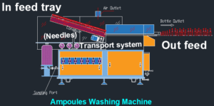
- This SOP is applicable for Preventive Maintenance of Ampoule Washing installed in the Production department.
- RESPONSIBILITY:
- Technician/ Operator shall be responsible for the proper execution of Preventive Maintenance of Ampoule Washing Machine as per SOP.
- Engineering – Head shall be responsible for reviewing the SOP and for ensuring the proper execution of preventive maintenance.
- ACCOUNTABILITY:
- Engineering – Head shall be accountable for proper implementation of the SOP.
- DEFINITIONS:
- Nil
- PROCEDURE:
- Preventive maintenance shall be executed as per the SOP No.: SOP/EN/XXXYYY – Execution of Preventive Maintenance.
- Ensure that the spare parts are available at the time of preventive maintenance.
- Preventive Maintenance – Mechanical
- Checking of fasteners
- Check that all the fasteners / mounting bolts of Ampoule Washing machine are properly tightened. There should not be any loose bolts, If found loose, tighten the bolts and nuts by using suitable spanners.
- Checking shall be done monthly.
- Checking of pneumatic tubes and fittings
- Physically check the pneumatic tubes and connectors for any damaged/leakage, if any damage/leak is observed, replace the tube/connector.
- Checking shall be done monthly.
- Checking of leakages.
- Check for any leakage of WFI from pipefitting and connectors. If any leakage is observed, check O-rings, gaskets and replace if found damaged OR worn out.
- Check all the clamps and tighten them if required.
- Check the leakages from WFI recirculation pumps at its inlet and outlet port, if any leakage is observed arrest the same by providing new gasket and tightening the line connectors.
- Checking shall be done six monthly.
- Checking of pumps
- Check the pump for any abnormal noise if found, Disconnect the pump motor wiring.
- Disconnect the pump from the pipeline and open the pump.
- Check the condition of bearings, mechanical seal, shaft, impeller and replace if found damaged.
- Checking of the pumps shall be done six monthly
- Checking and lubrication of bearings, chains, gears and sprockets.
- Check sprockets, gears, chain and cams for any damage. If found damaged, replace the same.
- Lubricate bearings, cams, gears, chain and sprocket with the help of grease gun.
- Checking shall be done monthly.
- Recommended Oil and grease for the lubrication as follows.
| Sr.No. | Lubricants | Type | Grade | Interval | Application |
| 1 | Grease | Mineral Oil | NLGI 0,1,2 | 1000 Hours | Bearing, Bushing, slides rollers, and cam followers |
| 2 | Oil | Mineral Oil | SAE 80W – 90, SAE 85W-140 | 300 Hrs | Gears, bearings and chains |
- Checking of Diaphragm Valve
- Check the valve for smoothly movements, if the operating hand wheel of valve is found jammed or stuck, then open the valve and carry out the maintenance as follows.
- Switch of the pump.
- Close the nearby upside and down side valves.
- Open the TC ends, loose the diaphragm valves nut by the Allen key, check the valve for damaged diaphragm, clean the valves, and check for the locking nut of diaphragm.
- If gasket found damaged (cut, leached, deform, shape and size change) change the diaphragm.
- After physically checking of diaphragm valve, refit in to the system and check for leakage and valve operation if found satisfactorily then it is okay otherwise replace the valve.
- For actuated diaphragm valve check for the performance of actuator for valve opening and closing as per interlocks of the system.
- Checking shall be done monthly.
- Cleaning of Utility inline Filters cartridge
- Check the reading of differential pressure gauges; if it filters get choked and not giving uniform flow; then the cleaning of cartridge filter is necessary.
- To clean the cartridge filter follows the following procedure.
- Close the inlet and outlet valves of filter.
- Open the drain plug, and drain out the hold water form filter housing; through close drain piping.
- Loose the body flange of cartridge filter housing.
- Remove the cartridge filter; check the condition of filter; if it is found damaged; then replace the same or sterilized the cartridge filter thoroughly and check for the integrity testing as per SOP “ Procedure for cleaning and Operation of Filter Integrity Test Instrument” SOP No. SOP/PR/XXXYYY
- Frequency of checking and replacement of filter cartridge shall be as needed.
- Checking of Filter housing
- Physical verify the filter housing for any damage, shape change, dents; surface roughness and end connections. If found, then rectify or replace the same.
- Checking of filter housing shall be done after every month.
- Checking of printer
- Check the printer for paper alignment and printer cartridge ribbon.
- Checking of printer shall be done after every six month.
- Checking of sprockets with chain alignment
- Check the loose or damaged chain or sprocket unbalanced, misalignment visually .if found damaged replace the same
- Checking of sprocket and chain alignment shall be done after every month.
- Preventive Maintenance – Electrical
- Checking of terminals and wiring
- Ensure that the main electrical supply to the machine is switched OFF.
- Visually check all the power & control wiring, terminals in the electrical panel and control elements mounted on the machine for any loose connection and tight them. If required.
- Check and ensure by using the screwdriver that all the wires are properly tightened at the distribution terminals inside the electrical panel and on the terminals of all the control elements.
- Checking shall be done six monthly.

- Checking of contactors
- Switch OFF the Electrical supply to the Machine.
- Remove all the power and control wires from the contactor terminals.
- Remove the dust from control panel with help of air blower.
- Remove the contactor from the panel and visually check all the contacts for the signs of pitting and deposit of carbon on the contacts.
- Clean the contacts, terminals and all the moving parts of the contactor by spraying contactor cleaner.
- Replace the contacts if found damaged / welded.
- Put back the contactor in the panel and re-terminate all the power and control wires properly to their original locations.
- Check the earthing of the panel body.
- A good earthing shall show less than 2 Volts between the Neutral Wire of the Incoming Power supply and Panel Body.
- Checking of contactors shall be done six monthly.
- Checking of PLC
- Check the PLC for blinking of LED.
- Check the display
- Check the wiring contacts, if required tight the same.
- Checking of PLC shall be done after every six month.
- Checking of motor
- Physically check the insulation resistance of motor winding with the help of megger.
- Check the phase continuity and winding continuity of motor with the help of tong tester.
- Physically check the motor terminal box and terminal connections.
- Check the voltage drawn by motor with the help of multimeter
- Check the current drawn by motor with the help of tong tester.
- Physically check the direction of rotation; it should be as per recommended direction.
- Checking shall be done after every six month.
- Check the stock of recommended spare part list as follows;
- Check the stock of recommended spare parts after every six month.
| Sr. No. | Description |
| 1 | Horizontal Gear Box Bracket |
| MAIN MOTOR | |
| Vertical Gear Box | |
| Reduction Gear Box | |
| 2 | BOTTOM PLATE |
| 3 | TIE BAR-1 |
| 4 | MAIN DRIVE SHAFT |
| 5 | DRIVE GEAR |
| 6 | SHAFT BRACKET |
| 7 | COUPLING |
| 8 | LIFTOR CAM |
| 9 | DRIVE GEAR |
| 10 | LEVER SHAFT |
| 11 | DRIVE LEVER |
| 12 | DRUM CAM |
| 13 | COLLAR |
| 14 | ROLLER PIN |
| 15 | OSCILLATING LINK |
| 16 | HOUSING |
| 17 | LEVER SHAFT |
| 18 | HOUSING BUSH |
| 19 | CAM LEVER |
| 20 | SPLIT COLLAR |
| 21 | DRIVE LEVER |
| 22 | SWIVEL GEAR -R.H |
| 23 | SWIVEL GEAR – L.H |
| 24 | SHAFT BRACKET BACK |
| 25 | IDLER LIFTING LEVER |
| 26 | SHAFT BRACKET |
| 27 | ARM – PIN |
| 28 | ARM – BUSH |
| 29 | LIFTER HOUSING |
| 30 | HOUSING BUSH |
| 31 | BELOW DISC |
| 32 | LIFTER SHAFT |
| 33 | RING SUPPORT BRACKET |
| 34 | NYLON SPACER |
| 35 | OSCILLATING RING ROLLER |
| 36 | ROLLER PIN |
| 37 | LIFTING ANGLE |
| 38 | BLOCK |
| 39 | ROLLER NEEDLE RING |
| 40 | OSCILLATING LINK |
| 41 | NEEDLE RING BRACKET |
| 42 | BELLOW DISC SPACER |
| 43 | DRIVE LEVER |
| 44 | OSCILLATING RING |
| 45 | LIFTING ANGLE |
| 46 | ROLLER NEEDLE RING |
| 47 | OSCILLATING LEVER DRIVEN |
| 48 | OSCILLATING LINK |
| 49 | BUSH OSCILLATING LINK |
| 50 | LINK PIN OSCILLATING |
| 51 | HOUSING |
| 52 | DRIVE LEVER |
| 53 | MAIN ROTATING DRUM |
| 54 | TURNING CAM |
| 55 | TURNING CAM SHAFT |
| 56 | DRUM BUSH |
| 57 | GEAR LEVER LH |
| 58 | GEAR LEVER RH |
| 59 | GEAR PIN LONG |
| 60 | GRIPPER |
| 61 | LINK PIN BUSH |
| 62 | BRASS SPACER |
| 63 | TURNING CAM PIN |
| 64 | GRIPPER BLOCK |
| 65 | JACKING HANDLE ROD |
| 66 | SHAFT SUPPORT |
| 67 | SUPPORT BUSH |
| 68 | DRIVE WORM (JACKING WORM SHAFT) |
| 69 | WORM WHEEL R.H. |
| 70 | HOUSING BUSH |
| 71 | IDLER SPROCKET |
| 72 | JACKING DRUM |
| 73 | DRIVEN SPROCKET 24 T |
| 74 | TURRET SHAFT ( 504 L NEW) |
| 75 | WORM COUPLING |
| 76 | WORM WHEEL |
| 77 | WORM WHEEL SHAFT (296 L NEW) |
| 78 | CLUTCH HUB |
| 79 | CLUTCH PLATE |
| 80 | SPRING |
| 81 | CHECK NUT |
| 82 | CLUTCH PIN |
| 83 | DRIVE DISC |
| 84 | DRIVEN SPROCKET 24 T |
| 85 | SPROCKET HUB |
| 86 | TURRET SHAFT ( 504 L NEW) |
| 87 | SHAFT HOUSING (NEW) |
| 88 | TURRET FLANGE |
| 89 | BASE PLATE |
- Checking of safety Alarms
- The following safety alarms shall be study at an after every six months intervals.
| Sr. No. | Alarms and Conditions | Alarm message | Control Action |
| 1 | RECYCLE LINE PRESSURE LOW Recycled water pressure is low in the pressure gauge. | Audio alarm is activated. OIT (operator Interface Terminal) displays the following alarm message (RECYCLE LINE PRESSURE LOW) | The machine stops. Reset the fault by pressing the RESET button after the required pressure is set. |
| 2 | RECYCLE LINE PRESSURE HIGH Recycled water pressure is high in the pressure gauge. | Audio alarm is activated. OIT (operator Interface Terminal) displays the following alarm message (RECYCLE LINE PRESSURE HIGH) | The machine stops. Reset the fault by pressing the RESET button after the required pressure is set. |
| 3 | PURIFIED LINE PRESSURE LOW Purified water pressure is low in the pressure gauge. | Audio alarm is activated. OIT (operator Interface Terminal) displays the following alarm message (PURIFIED LINE PRESSURE LOW) | The machine stops. Reset the fault by pressing the RESET button after the required pressure is set. |
| 4 | PURIFIED LINE PRESSURE HIGH Purified water pressure is high in the pressure gauge. | Audio alarm is activated. OIT (operator Interface Terminal) displays the following alarm message (PURIFIED LINE PRESSURE HIGH) | The machine stops. Reset the fault by pressing the RESET button after the required pressure is set. |
| 5 | WFI LINE PRESSURE LOW WFI pressure is low in the Pressure gauge. | Audio alarm is activated. OIT (operator Interface Terminal) displays the following alarm message (WFI LINE PRESSURE LOW) | The machine stops. Reset the fault by pressing the RESET button after the required pressure is set. |
| 6 | WFI LINE PRESSURE HIGH WFI pressure is high in the Pressure gauge. | Audio alarm is activated. OIT (operator Interface Terminal) displays the following alarm message (WFI LINE PRESSURE HIGH) | The machine stops. Reset the fault by pressing the RESET button after the required pressure is set. |
| 7 | COMP AIR LINE PRESSURE LOW Compressed air pressure is low in the pressure gauge. | Audio alarm is activated. OIT (operator Interface Terminal) displays the following alarm message (COMP AIR LINE PRESSURE LOW) | The machine stops. Reset the fault by pressing the RESET button after the required pressure is set. |
| 8 | COMP AIR LINE PRESSURE HIGH Compressed air pressure is high in the pressure gauge. | Audio alarm is activated. OIT (operator Interface Terminal) displays the following alarm message (COMP AIR LINE PRESSURE HIGH) | The machine stops. Reset the fault by pressing the RESET button after the required pressure is set |
| 9 | RECYCLE WATER TANK LEVEL LOW The level in the recycle water tank is low. | Audio alarm is activated. OIT (operator Interface Terminal) displays the following alarm message (RECYCLE WATER TANK LEVEL LOW ) | The machine stops. Put the required amount of water in the tank. Reset the fault by pressing the RESET button. |
| 10 | RECYCLE WATER TANK TEMPERATURE LOW The temperature in the recycle water tank is low. | Audio alarm is activated. OIT (operator Interface Terminal) displays the following alarm message (RECYCLE WATER TANK TEMPERATURE LOW) | The machine stops. Check the RTD connection. Reset the fault by pressing the RESET button. |
| 11 | RECYCLE WATER TANK TEMPERATURE HIGH The temperature in the recycle water tank is high. | Audio alarm is activated. OIT (operator Interface Terminal) displays the following alarm message (RECYCLE WATER TANK TEMPERATUREHIGH) | The machine stops. Check the RTD connection. Reset the fault by pressing the RESET button. |
| 12 | PROTECTION GUARD OPEN Protection guard is open in AUTO mode. | Audio alarm is activated. OIT (operator Interface Terminal) displays the following alarm message (PROTECTION GUARD OPEN) | The machine stops. Keep the guard in position. Reset the fault by pressing the RESET button. |
| 13 | INFEED TORQUE OVERLIMIT The infeed turret stops when the sensor is not in correct position. | Audio alarm is activated. OIT (operator Interface Terminal) displays the following alarm message (TURRET JAM) | The machine stops. Place the sensor in position. Reset the fault by pressing the RESET button |
| 14 | OUTFEED TORQUE OVERLIMIT The outfeed turret stops when the sensor is not in correct position. | Audio alarm is activated. OIT (operator Interface Terminal) displays the following alarm message (TURRET JAM) | The machine stops. Place the sensor in position. Reset the fault by pressing the RESET button. |
| 15 | EMERGENCY STOP Emergency push button is pressed. | Audio alarm is activated. OIT (operator Interface Terminal) displays the following alarm message (EMERGENCY STOP) | The machine stops. Release the emergency push button. Reset the fault by pressing the RESET button. |
| 16 | MOTOR OVERLOAD The main motor stops so the infeed conveyor motor also stops. | Audio alarm is activated. OIT (operator Interface Terminal) displays the following alarm message (MOTOR OVERLOAD) | The machine stops. Reset the fault by pressing the RESET button after the motor load is set. |
| 17 | MAX ACCUMULATION AT OUTFEED The machine stops due to max accumulation of vials at outfeed. | Audio alarm is activated. OIT (operator Interface Terminal) displays the following alarm message (MAX ACCUMULATION AT OUTFEED) | The machine stops. Check at the outfeed for max accu. Reset the fault by pressing the RESET button. |
| 18 | WFI LINE TEMPERATURE LOW The temperature in the WFI line is low. | Audio alarm is activated. OIT (operator Interface Terminal) displays the following alarm message (WFI LINE TEMPERATURE LOW) | The machine stops. Reset the fault by pressing the RESET button after the temperature is set |
| 19 | WFI LINE TEMPERATURE HIGH The temperature in the WFI line is high. | Audio alarm is activated. OIT (operator Interface Terminal) displays the following alarm message (WFI LINE TEMPERATURE HIGH) | The machine stops. Reset the fault by pressing the RESET button after the temperature is set |
| 20 | WFI LINE RTD FAULT The WFI Line RTD fault occurs. | Audio alarm is activated. OIT (operator Interface Terminal) displays the following alarm message (WFI LINE RTD FAULT ) | The machine stops. Reset the fault by pressing the RESET button. |
| 21 | RECYCLE WATER TANK RTD FAULT The recycle water tank RTD fault occurs. | Audio alarm is activated. OIT (operator Interface Terminal) displays the following alarm message (RECYCLE WATER TANK RTD FAULT ) | The machine stops. Reset the fault by pressing the RESET button. |
| 22 | RECYCLE LINE TRANSDUCER FAULT The sensor for pressure transducer in recycle water line fault occurs. | Audio alarm is activated. OIT (operator Interface Terminal) displays the following alarm message (RECYCLE LINE TRANSDUCER FAULT) | The machine stops. Reset the fault by pressing the RESET button after the sensor position is set. |
| 23 | COMPRESSED AIR LINE TRANSDUCER FAULT The sensor for pressure Transducer in CA line fault occurs. | Audio alarm is activated. OIT (operator Interface Terminal) displays the following alarm message (COMPRESSED AIR LINE TRANSDUCER FAULT) | The machine stops. Reset the fault by pressing the RESET button after the sensor position is set |
| 24 | PURIFIED WATER LINE TRANSDUCER FAULT The sensor for pressure Transducer in purified water line fault occurs. | Audio alarm is activated. OIT (operator Interface Terminal) displays the following alarm message (PURIFIED WATER LINE TRANSDUCER FAULT) | The machine stops. Reset the fault by pressing the RESET button after the sensor position is set. |
| 25 | WFI LINE TRANSDUCER FAULT The sensor for pressure transducer in WFI line fault Occurs. | Audio alarm is activated. OIT (operator Interface Terminal) displays the following alarm message (WFI LINE TRANSDUCER FAULT) | The machine stops. Reset the fault by pressing the RESET button after the sensor position is set. |
- Post Preventive Maintenance – Check List
- Record the Preventive Maintenance details as per the Format No.: SOP/EN/XXXYYY “Preventive Maintenance Checklist & Record for Ampoule Washing Machine”.
- Whenever any modifications and major works are carried out to the equipment, the same shall be mentioned in the equipment history card as per the respective SOP.
- Connect the equipment main power supply and start the equipment.
- Ensure that the equipment is running smoothly, without any abnormality.
- If any abnormality is observed in the above, same will be attended in co-ordination with User department Head.
- ABBREVIATIONS:
- CRF No. : Change Request Form number
- QA : Quality Assurance
- MMI : Man Machine Interface
- WFI : Water for Injection
- REFERENCES:
- Operational & Maintenance Manual of Ampoule Washing Machine.
- DISTRIBUTION LIST:
- SOP shall be distributed to following departments Quality Assurance, Engineering as per user request
- ANNEXURES:
- Preventive maintenance checklist and record for :SOP/EN/XXXYYY Ampoule Washing Machine
PREVENTIVE MAINTENANCE CHECKLIST & RECORD FOR AMPOULE WASHING MACHINE
| Equipment Name | Location | ||
| Equipment ID | Frequency |
| Things to be done: | Check List | Remarks |
| Monthly Check List | ||
| Checking of fasteners; mounting bolts. | ||
| Checking of pneumatic tubes and fittings. | ||
| Checking of lubrication of bearings; chains; gears and sprockets. | ||
| Checking of diaphragm valves. | ||
| Checking of filter housing. | ||
| Checking the alignment of sprockets with chain and its condition. | ||
| Checking of shaft couplers. | ||
| Checking of radial play of CAMs to the Shats. | ||
| Quarterly Check List | ||
| Checking of recycled water circulation pump | ||
| Checking of conveyor belts. | ||
| Checking of grippers, Gripper block, springs and gripper bush. | ||
| Checking of Oscillating ring rollers. | ||
| Checking of Exhaust System. | ||
| Half Yearly Check List | ||
| Checking of vacuum pumps. | ||
| Checking of the printer | ||
| Checking of terminal and wiring | ||
| Checking of motor. | ||
| Checking of PLC. | ||
| Checking of contactors. | ||
| Check the safety alarms. | ||
| Checking of leakages. | ||
| Checking of pumps. |